Energy AI Project

Embedded Multisensor UAV Imaging System for Environmental Monitoring

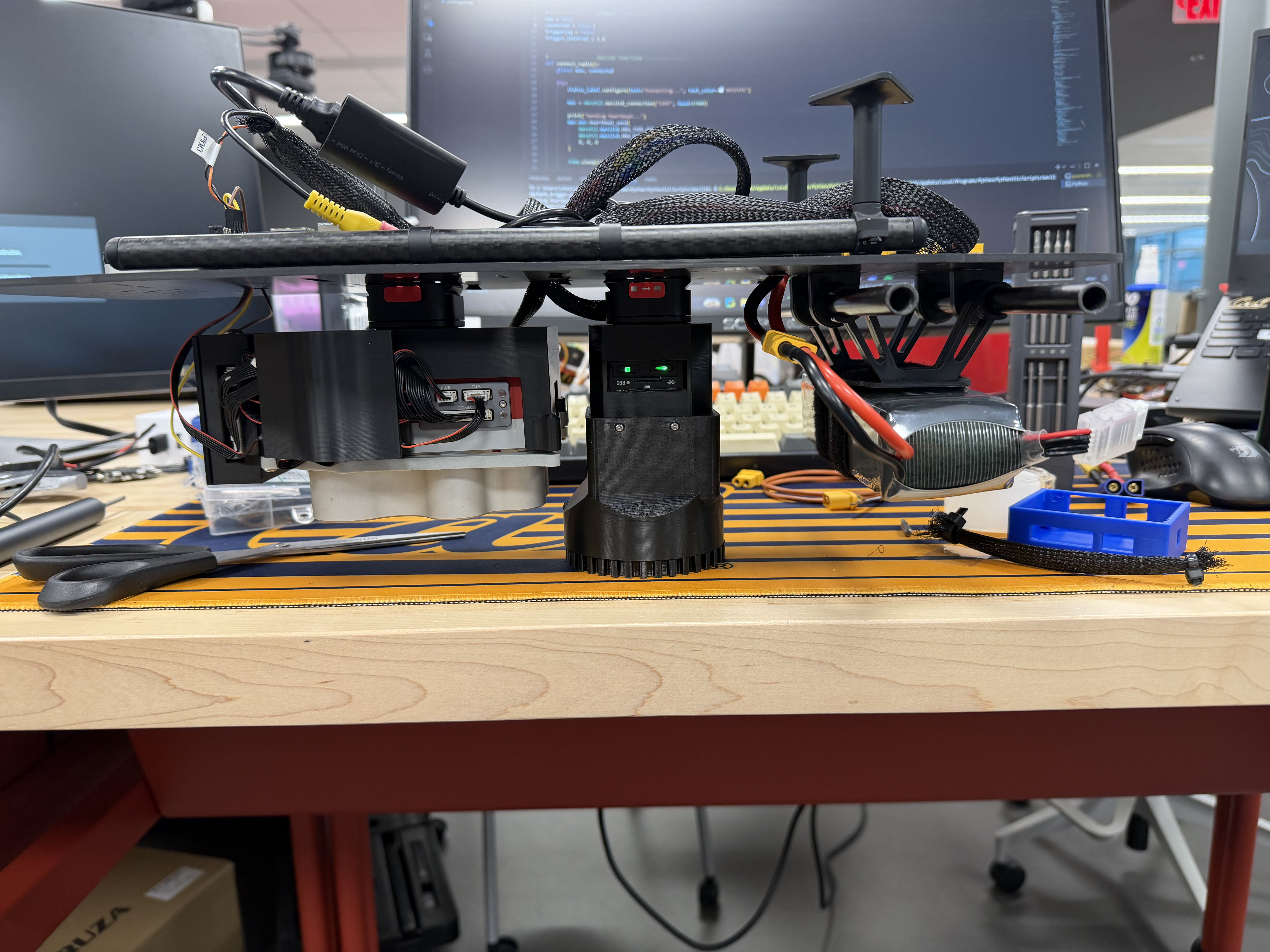
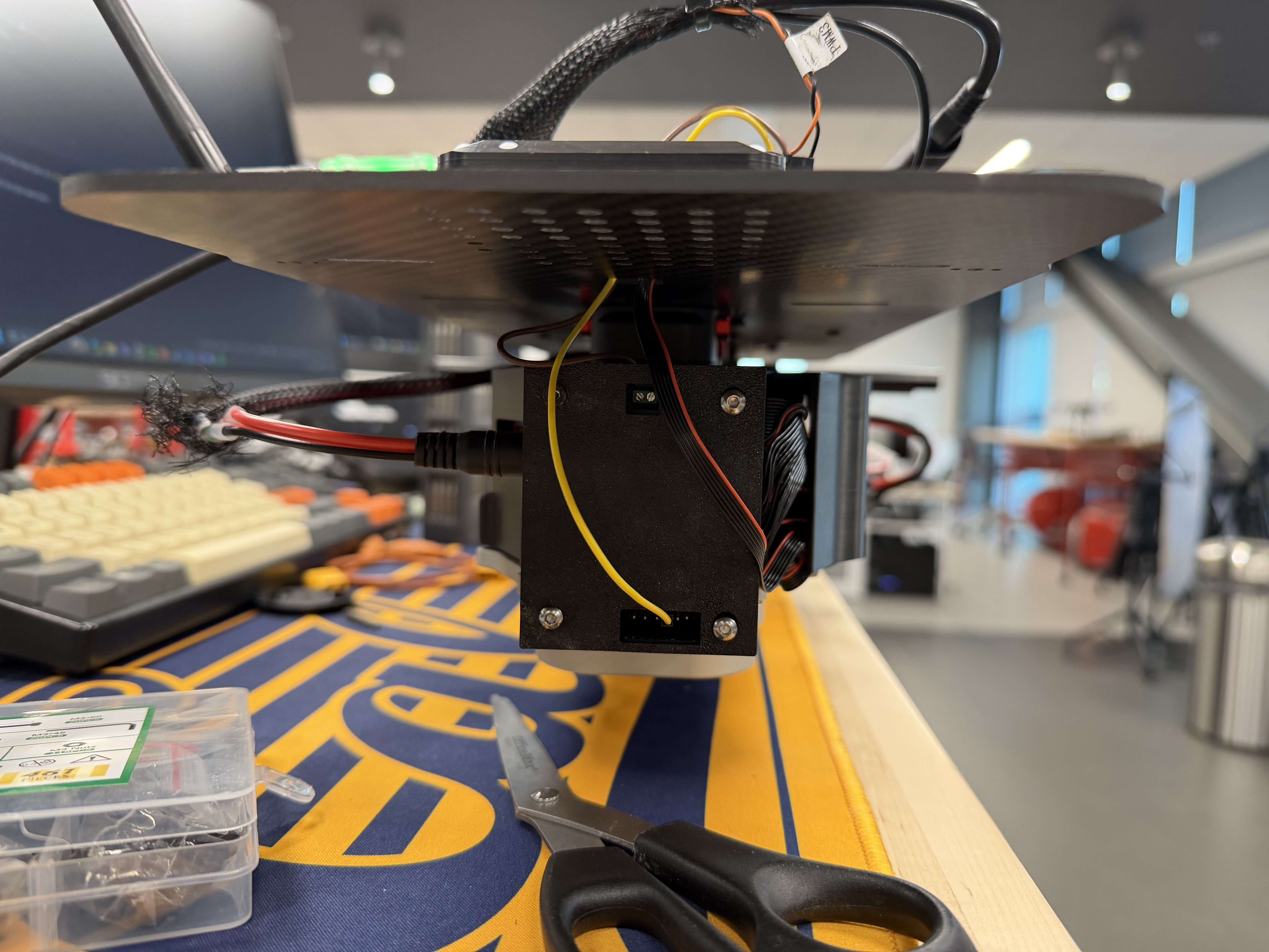
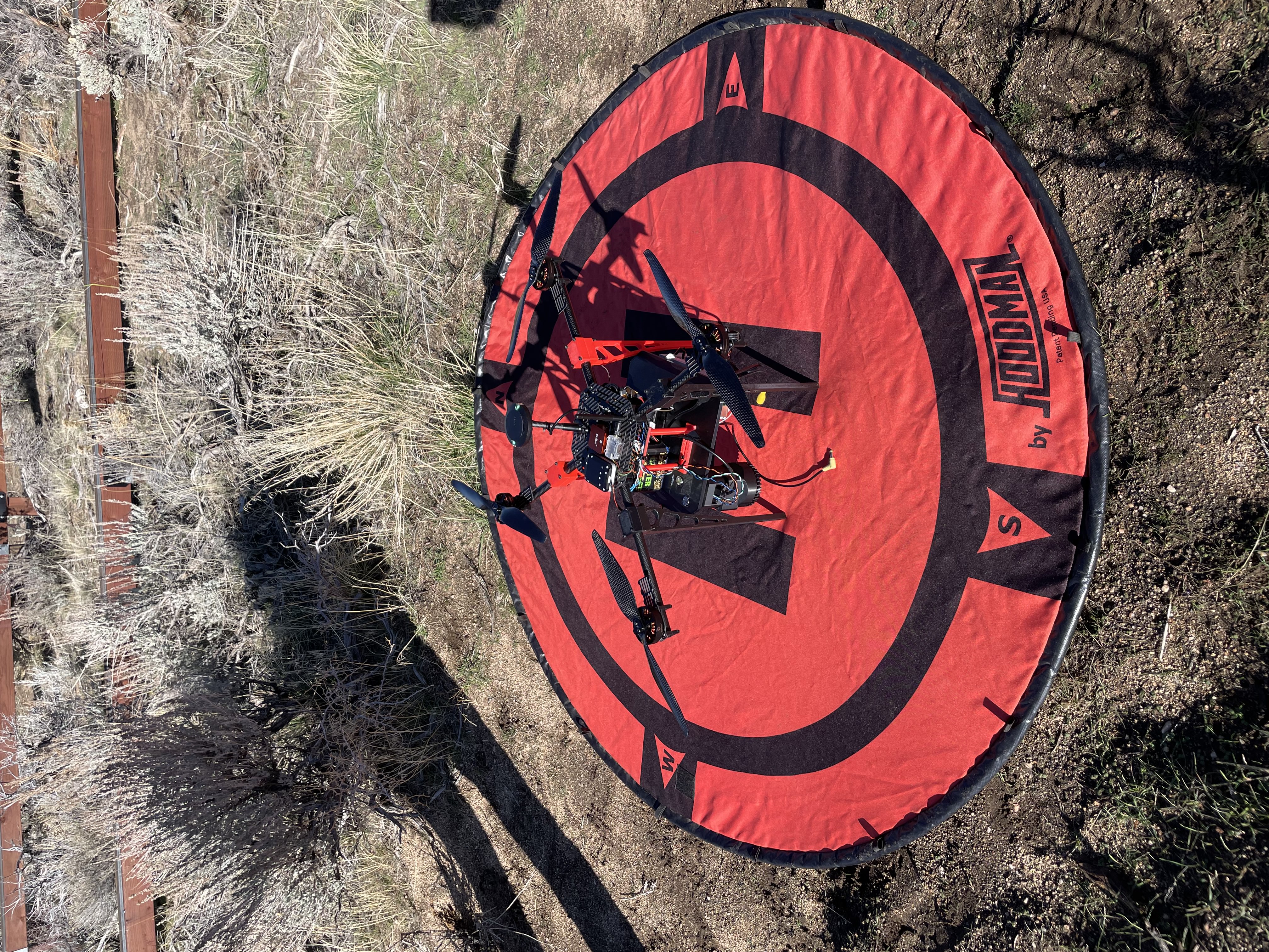
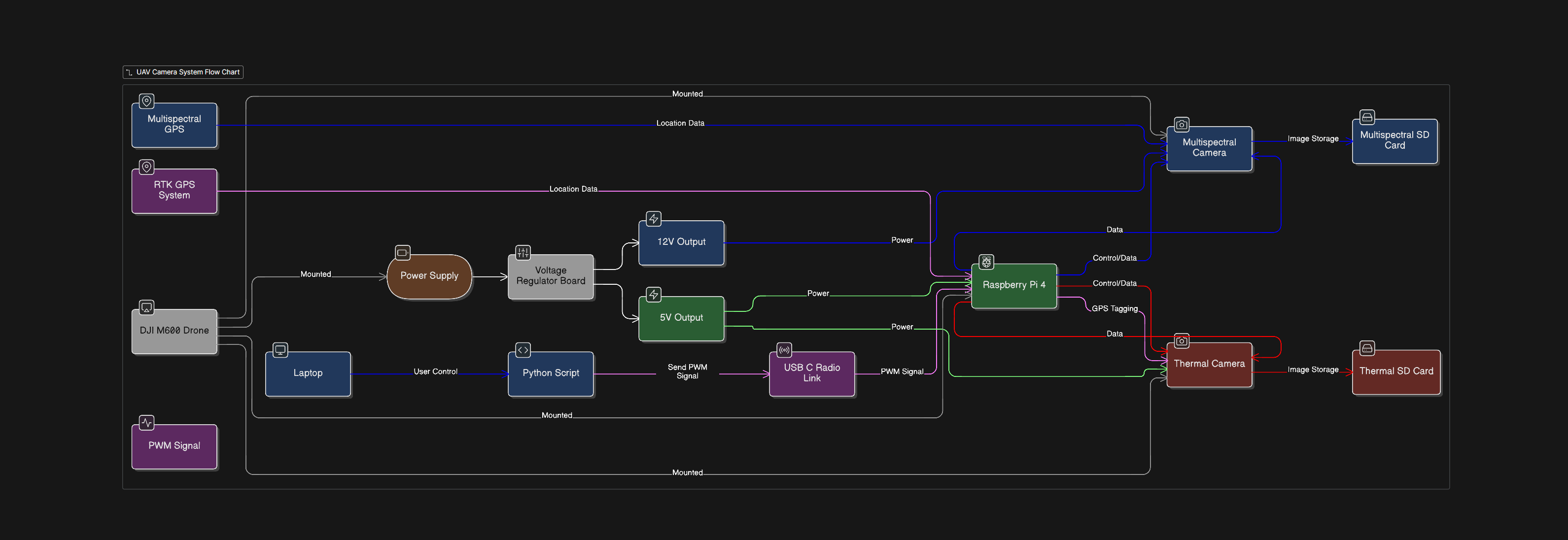
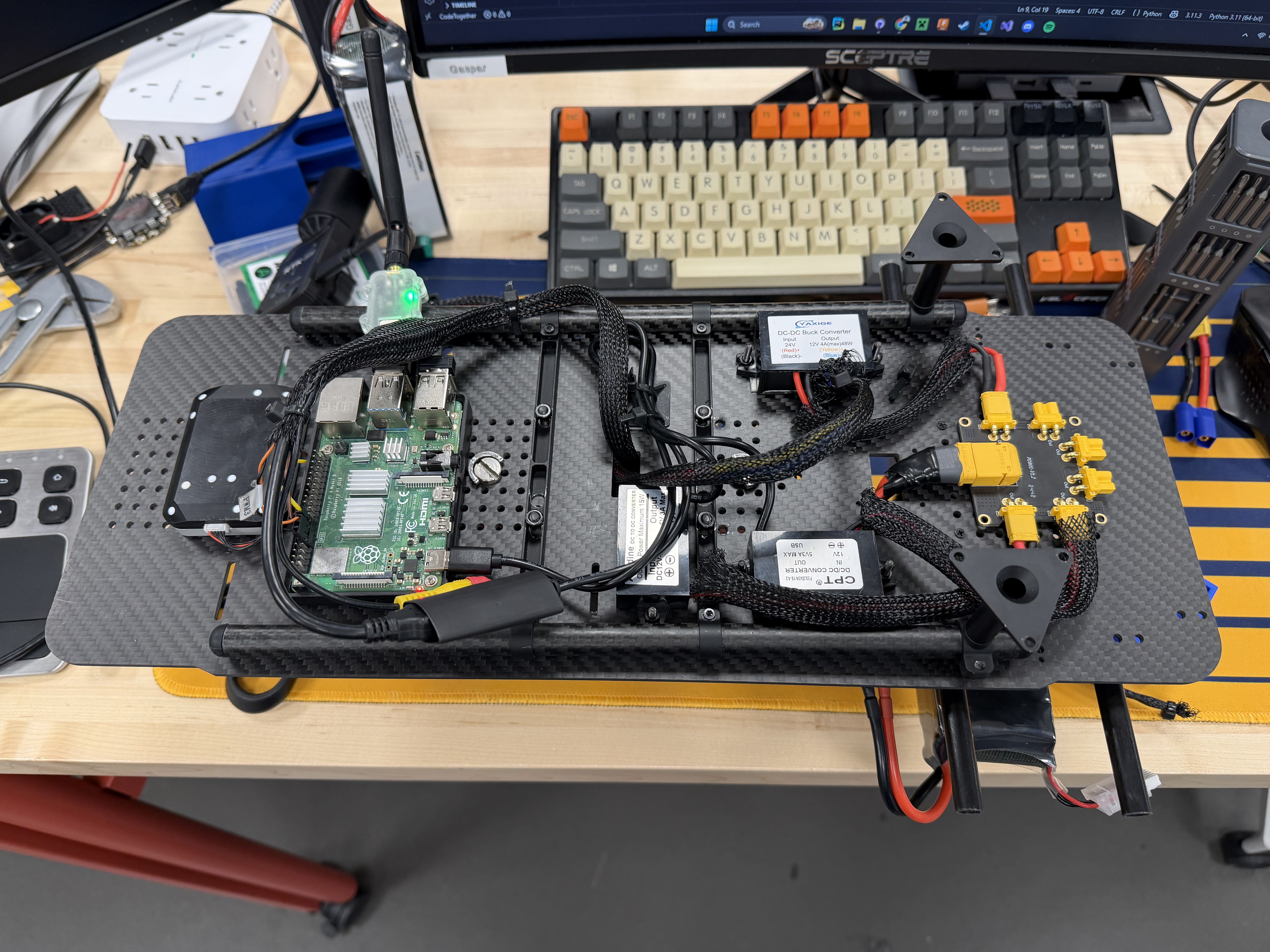
This project is an embedded systems project that controls and coordinates multiple devices on a drone. The main controller is a Raspberry Pi 4, which acts as the onboard computer for the system. It receives commands from a laptop ground station through a radio link and then sends the correct electrical signals to trigger a thermal camera and a multispectral camera during flight. The Raspberry Pi also collects GPS data, including position and time, and saves that information each time an image is captured. This makes it possible to match each image with where and when it was taken. In addition to the software, the project includes power regulation, communication between onboard and ground hardware, and custom 3D-printed mounts to hold the cameras and electronics securely on the drone. This project shows embedded systems skills in hardware and software integration, sensor control, wireless communication, GPIO and PWM signal use, and real-time data logging. The full system was designed to support real-world tasks such as wildfire monitoring, vegetation analysis, and other forms of environmental sensing.

What I Learned: Through this project, I learned how to work with a Raspberry Pi in much more detail, starting from installing the operating system and setting up the board to running my own Python code on it. I also learned how to install and use important Python libraries, such as pymavlink, to communicate with the radios and send commands between the ground station and the drone system. On the hardware side, I learned how to use GPIO pins and PWM signals with duty cycles to control devices like the cameras. I also learned how important it is to correctly geotag images and keep the GPS data in sync with the camera trigger pulses so that the collected data is accurate and useful. In addition, I learned how to design 3D-printed parts that are lightweight but still strong enough to hold the system securely, since keeping the mounts light helps improve flight time and overall drone performance.
Mavlink Python Raspberry PI 4 Radio Communication RTK GPS System View GitHub Repo
Energy AI Project

Multi-Sensor UAV (Dual Payload)

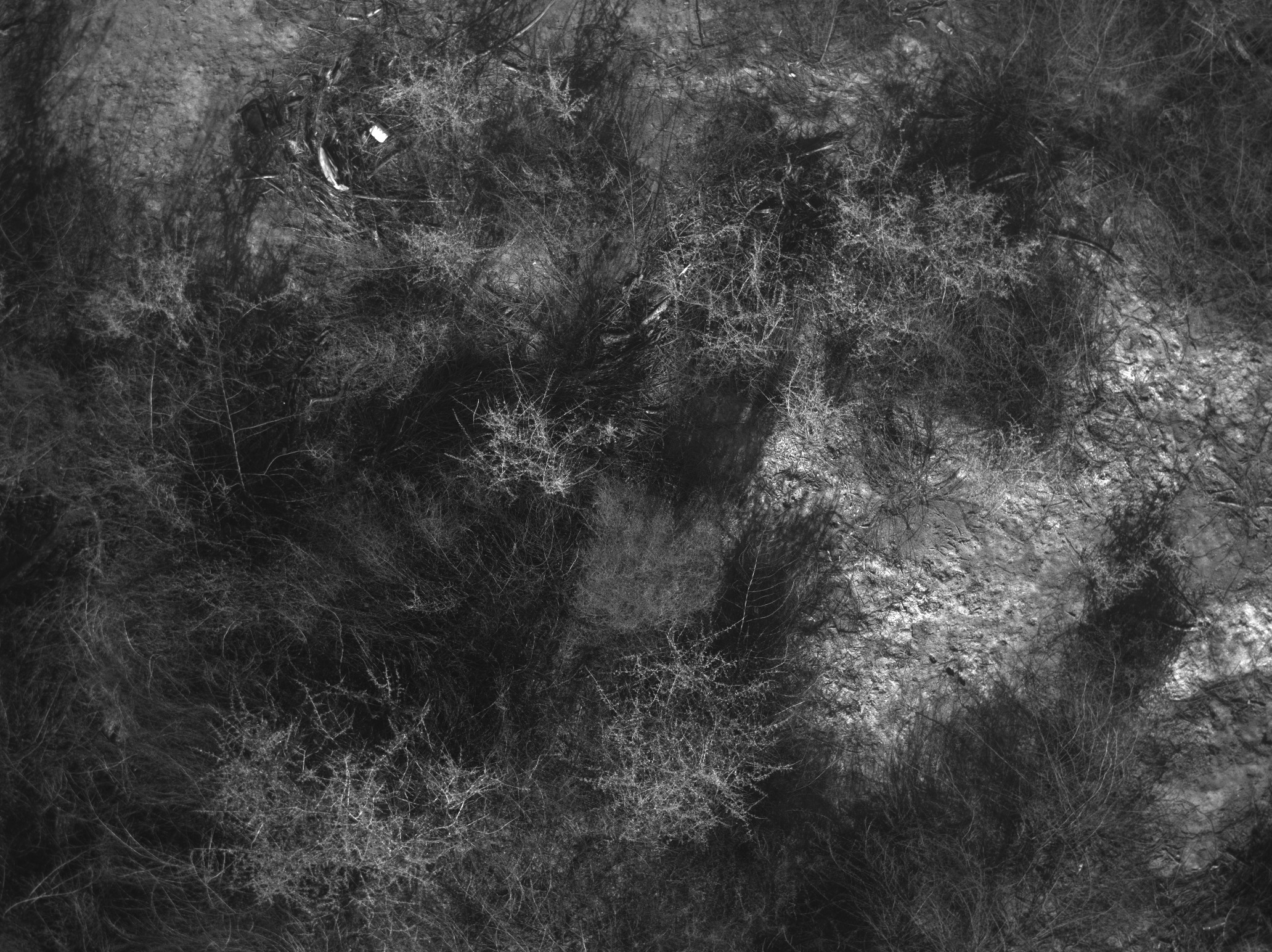
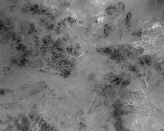
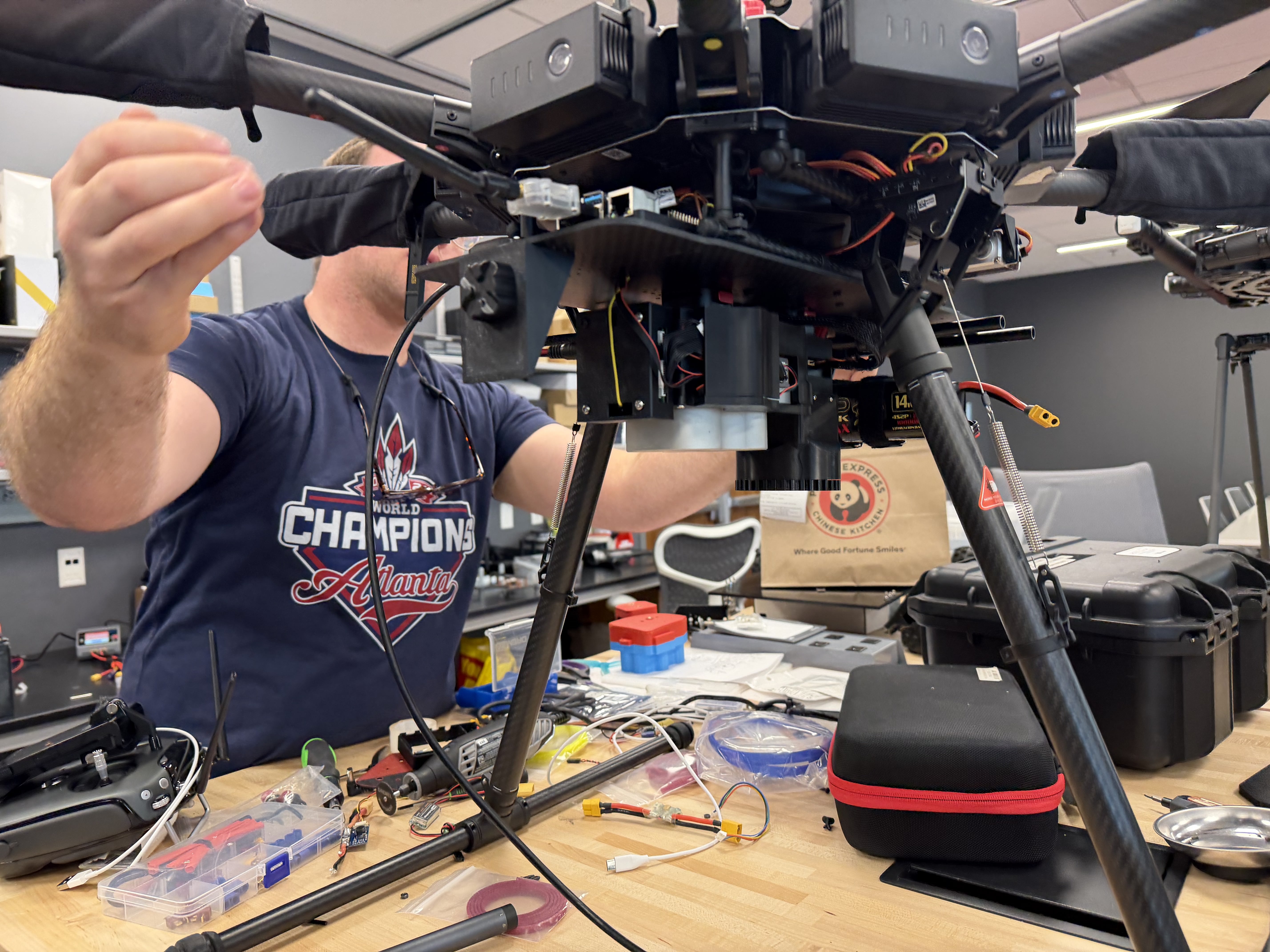
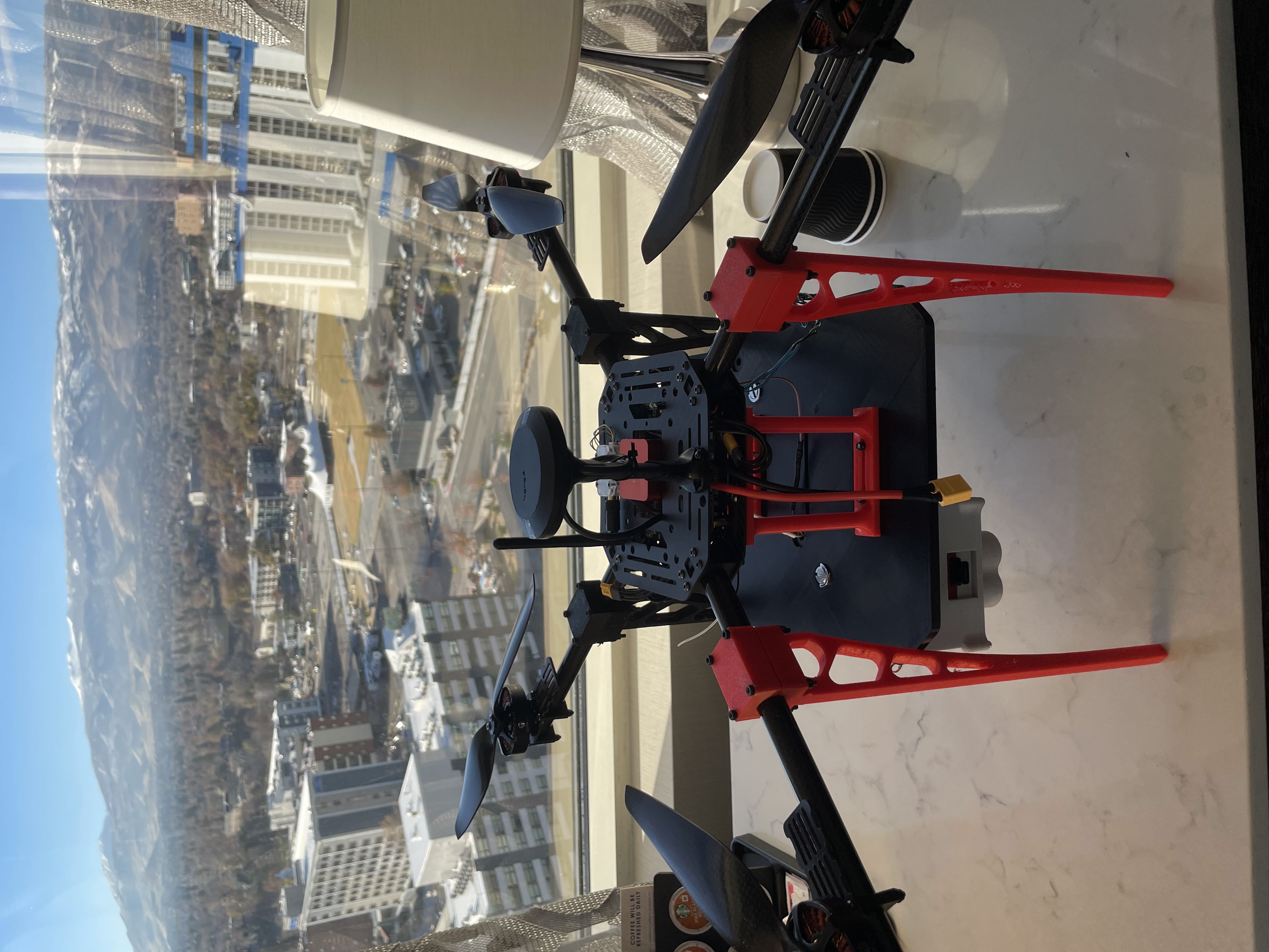
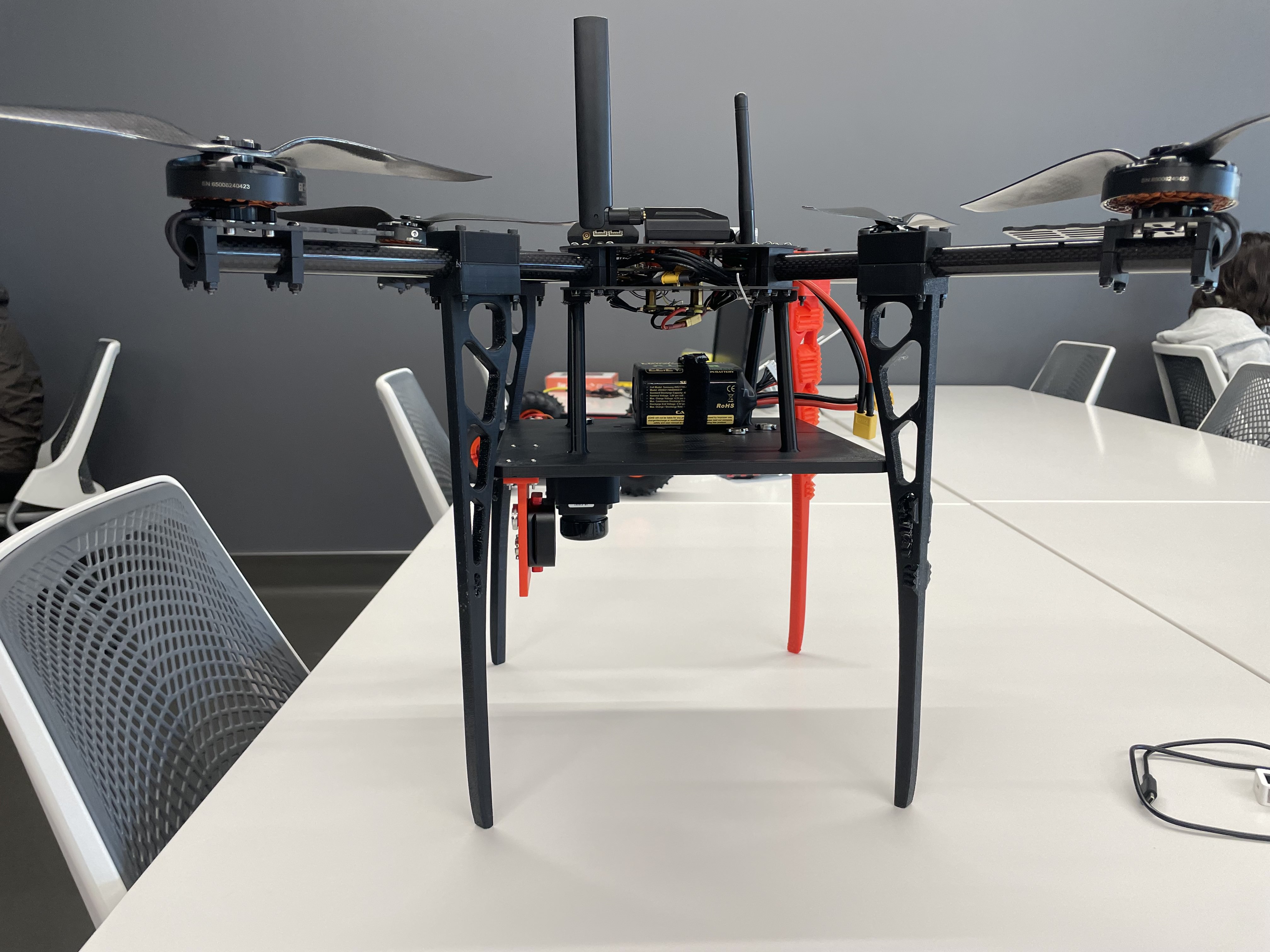
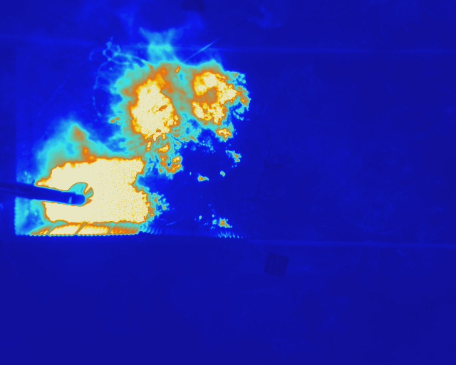
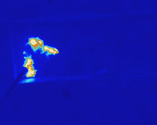
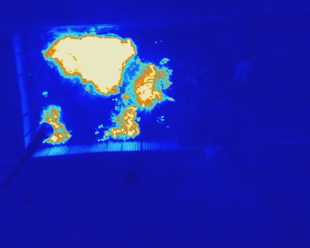
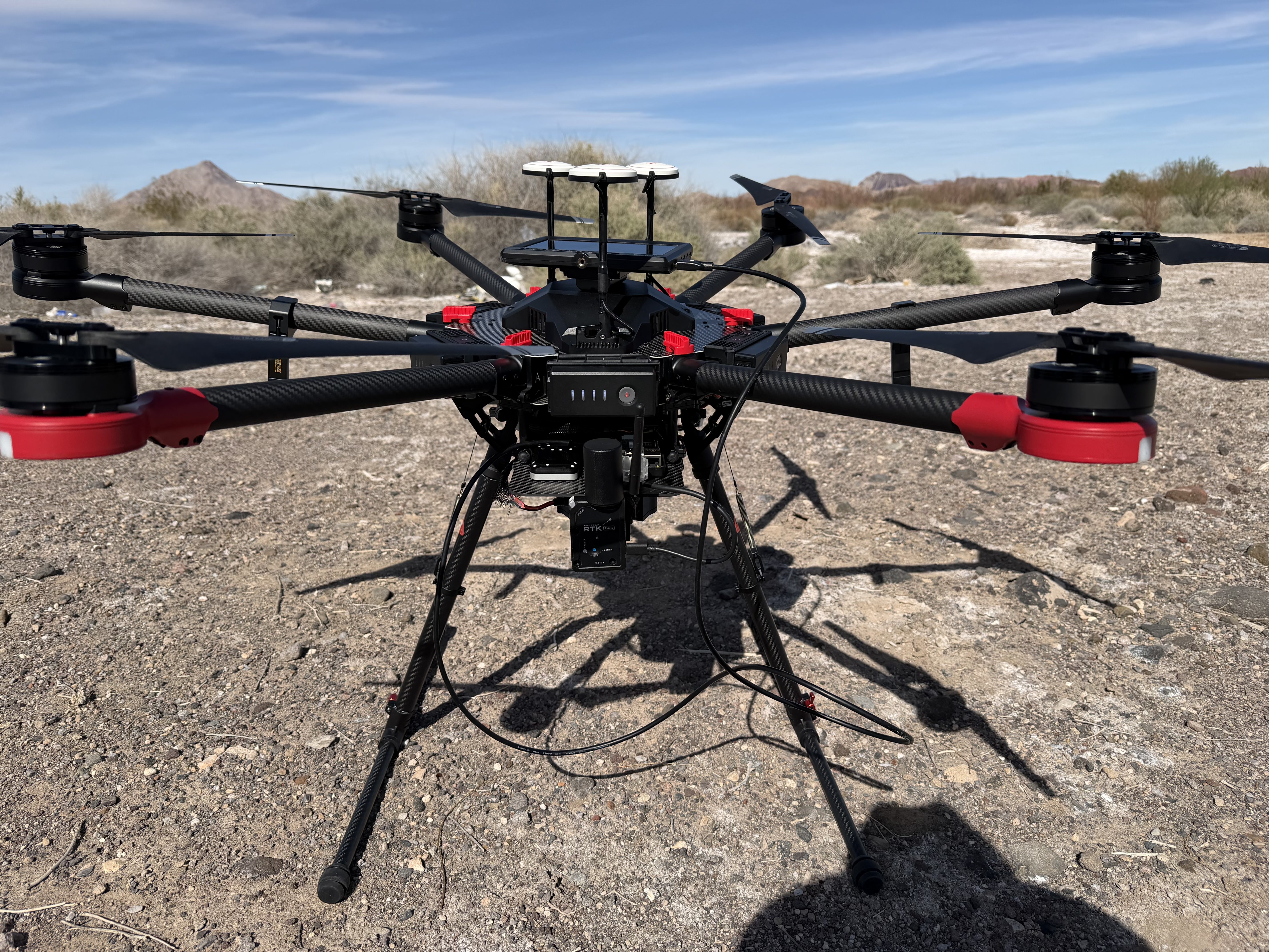
This drone is a custom-built dual-sensor platform designed specifically for wildfire data collection. It carries a FLIR Vue Pro R thermal camera and an Altum PT multispectral sensor, giving me the ability to capture both heat signatures and detailed spectral information during flights. I designed the entire camera mounting plate in SolidWorks and 3D-printed it in lightweight PLA so the system stays stable without adding unnecessary weight. The drone runs on an OrangeCube flight controller, which handles stabilization, navigation, and autonomous flight paths. I’ve already used this setup to collect high-resolution thermal and multispectral imagery over burn sites, allowing me to study fire behavior, vegetation conditions, and post-fire environmental changes with much greater detail.

What I Learned: Through this project, I gained extensive hands-on experience working with UAVs, from flight controller setup to payload integration. Designing the camera mounting plate pushed me deeper into the mechanical engineering side of things I spent a lot of time iterating in SolidWorks, testing fits, and refining a structure that was both lightweight and strong, which really sharpened my design and prototyping skills. I also learned how to integrate self-triggering sensors into a UAV workflow, making sure the FLIR and Altum PT could operate reliably during autonomous missions. Most importantly, I learned how to apply my own custom-built instrument within a larger scientific research effort as part of the HDRFS program, contributing meaningful data and gaining real experience in field-based environmental research.

3D - Design QgroundControl SolidWorks Mission Planner
Main project image

Motorized 3-Axis Camera Gantry

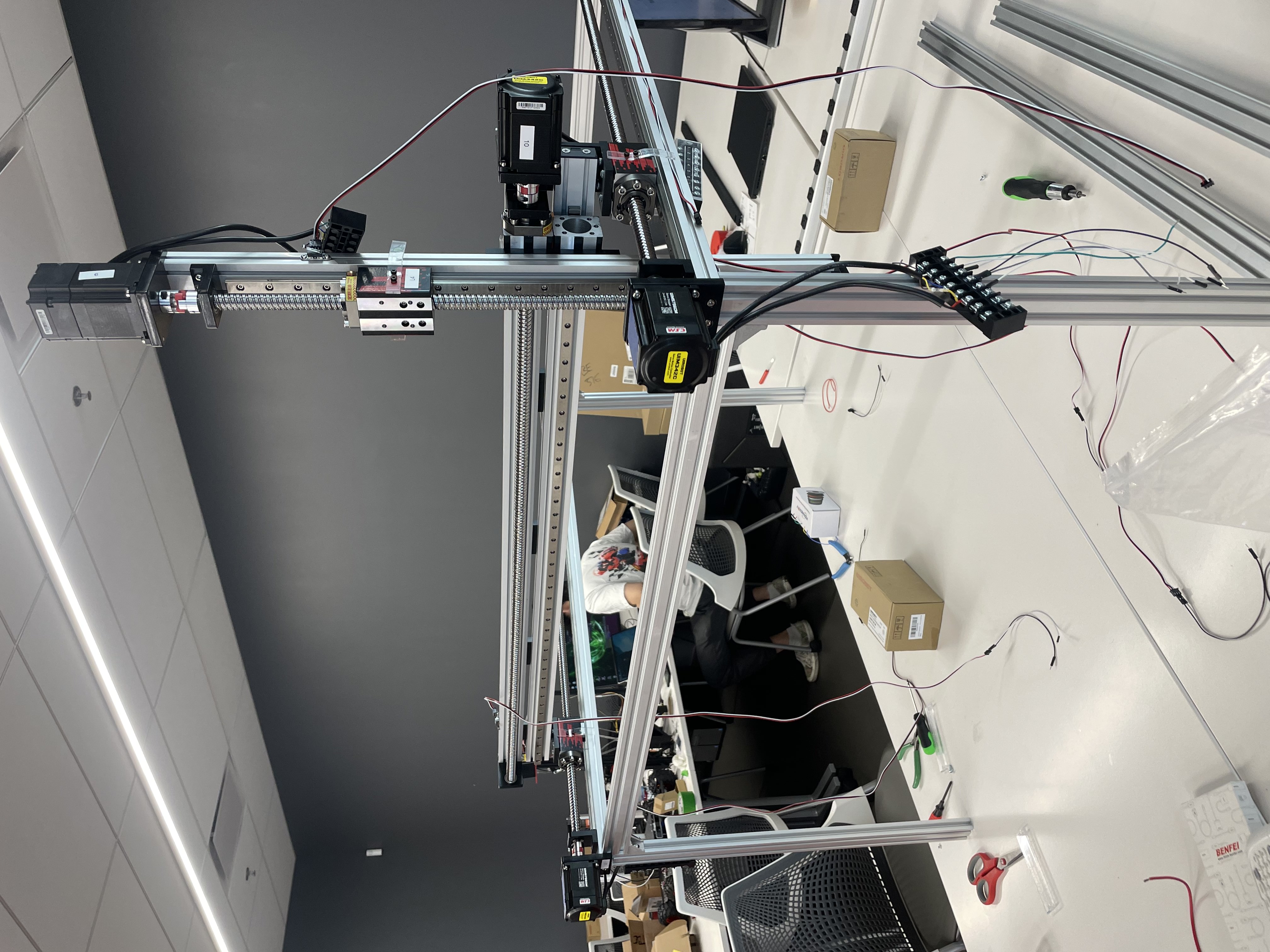
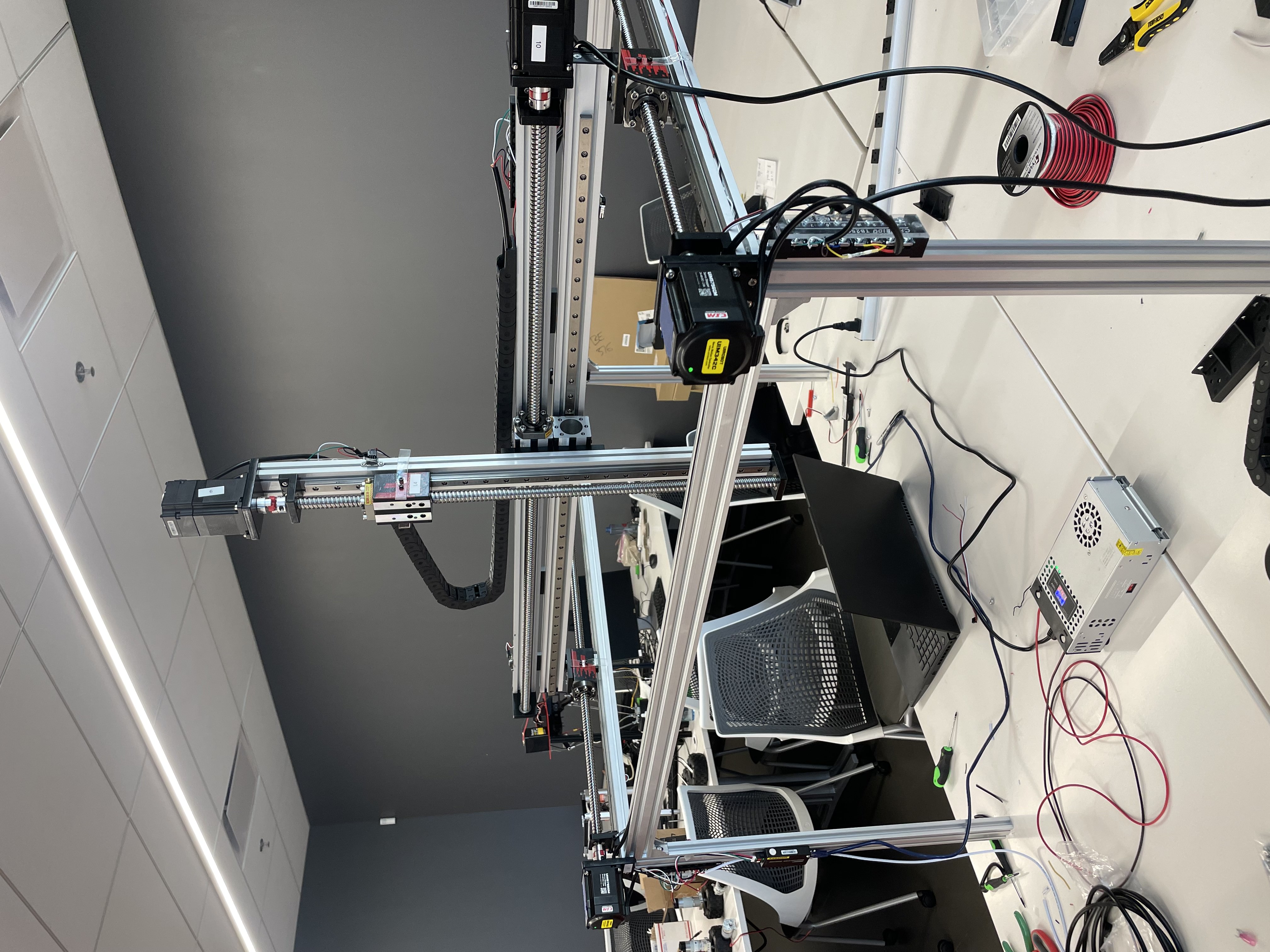
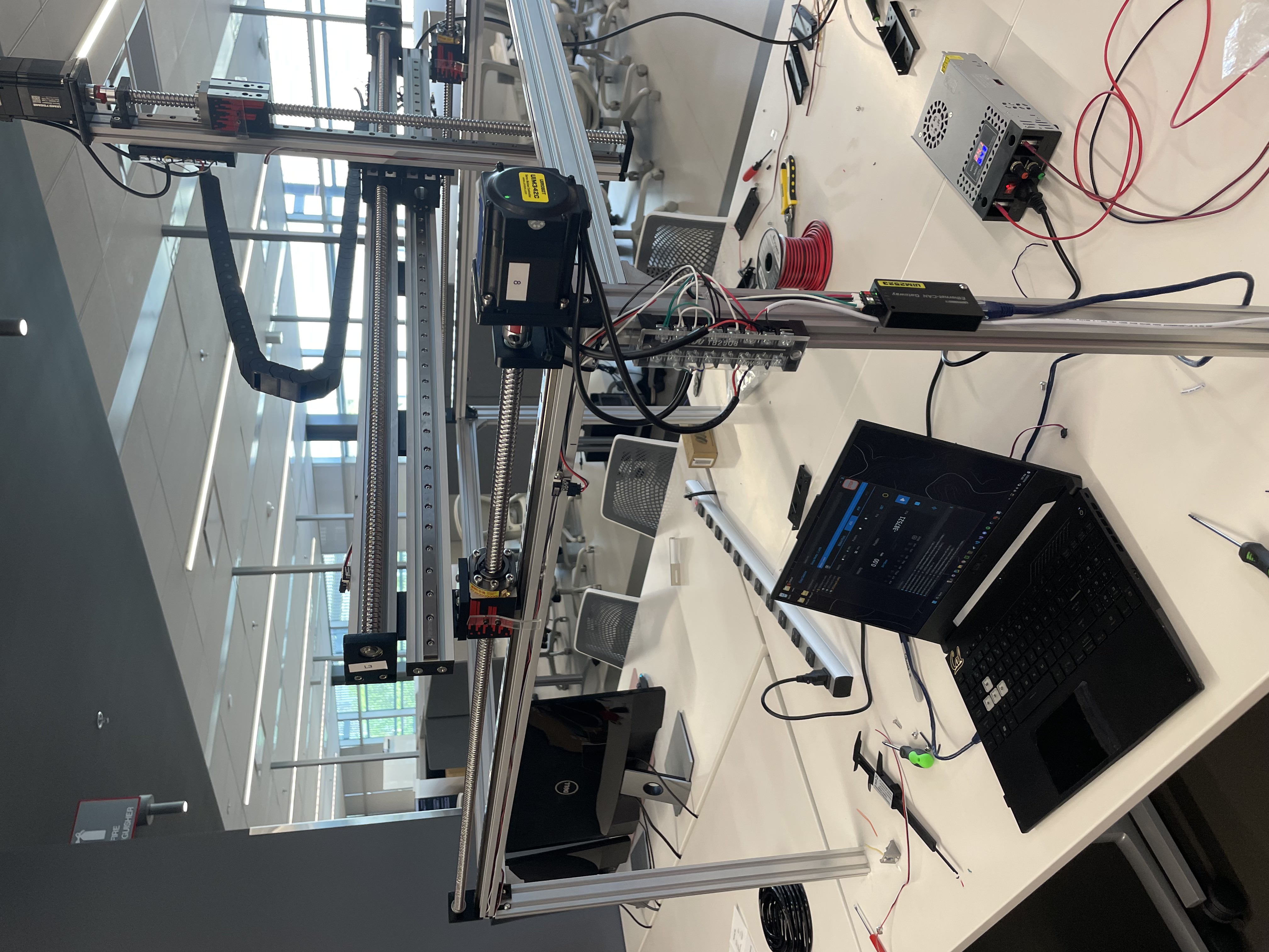
I worked to the full design and setup of this 3-axis camera gantry system. I used UIM5756CM stepper motors with FUYU linear rail modules to control precise movement along the X, Y, and Z axes. To protect the system, I implemented mechanical limit switches on each axis and designed custom Acrylic strikers I cut and shapped to ensure the motors stopped before reaching the physical limits. I soldered custom cable extensions, wired all components in series, and organized the wiring using terminal blocks. The entire system runs on a regulated power supply that provides the correct voltage and current to safely drive all motors. Communication with the motors is handled through a 2523UIM gateway over Ethernet, allowing stable and accurate control from a remote interface.

What I learned:This project gave me hands-on experience with building a full motion control system from scratch. I used the 2523UIM gateway to control stepper motors over Ethernet and learned how to properly wire high-power components by soldering custom cable extensions, wiring everything in series, and organizing connections with terminal blocks. I also matched the power supply to the motors to ensure stable voltage and current. To prevent overtravel, I installed mechanical limit switches on each axis and designed custom acrylic strikers by cutting and shaping them myself. This process taught me a lot about hardware integration, safe motion control, and combining electronics with mechanical design.

StepEva3 Stepper Motors C++ CAN Bus Soldering Designer